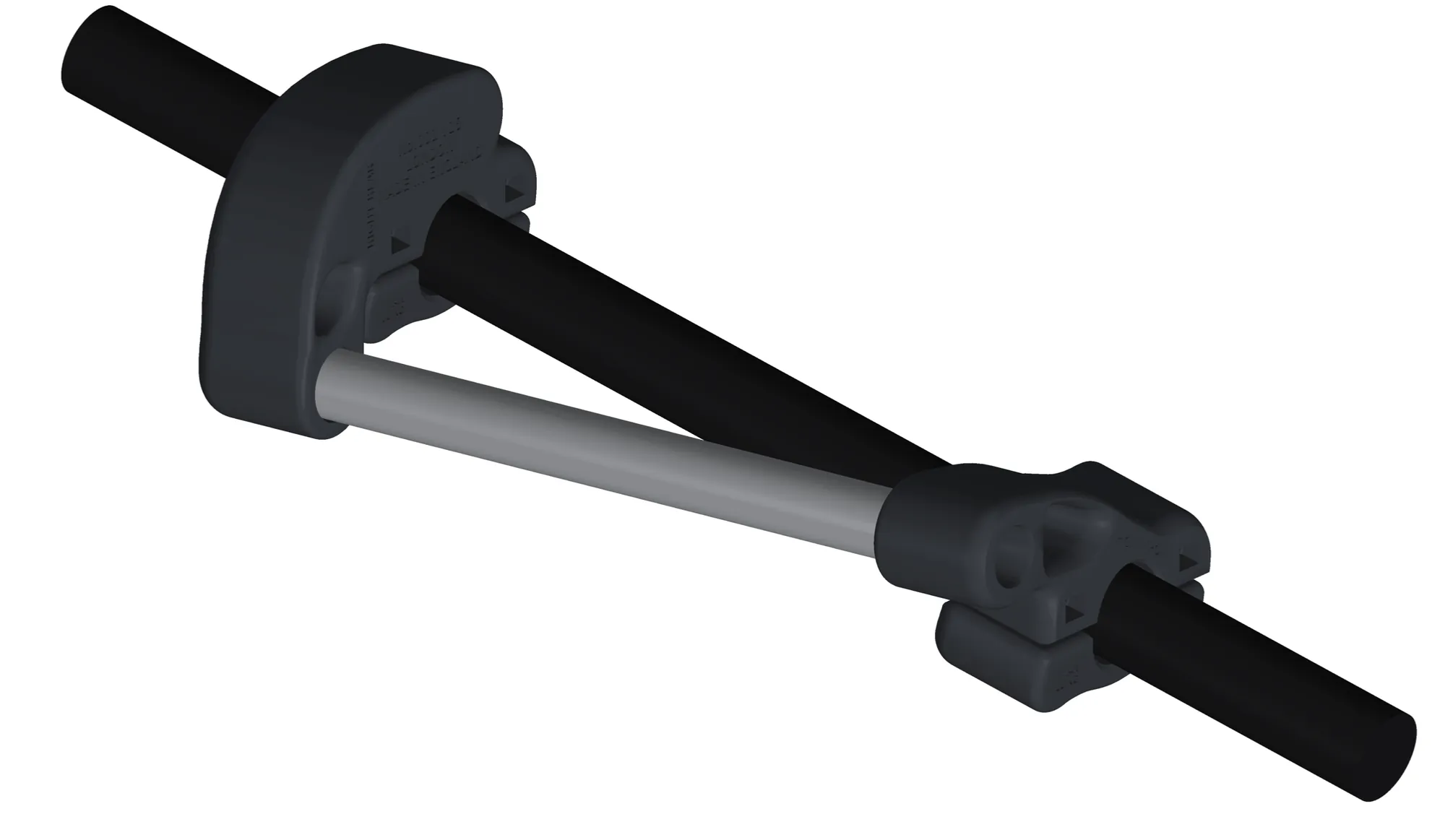
A level rail.
A 16 mm aluminium rail held level beside the rising tube, clamped on without drilling the rack.
 E-Cruiza pannier system
Engineering notebook / Pedibal E-Cruiza
A clamp-on pannier system for my e-bike’s rear rack. Designed in code, stress-tested in simulation and printed at home, one version at a time.
Nothing on this page is for sale and I’m not taking orders. It’s a record of the problem, the designs, the tests and the changes I made at each stage.
01 / The need
My Decathlon 20 L panniers hang from KLICKfix Vario hooks, which want a level rail between 8 and 16 mm. My Pedibal E-Cruiza’s rack has a 21.6 mm round top tube that rises 14° towards the rear. Hooked straight on, the bags sit crooked, on a tube too big for the hooks.
A 16 mm aluminium rail held level beside the rising tube, clamped on without drilling the rack.
The bag’s lower strap expects a side-stay the rack doesn’t have, so a loaded bag swings towards the wheel: about 44 N parked, 190 N over a pothole.
The bench seat leaves no seatpost for my iGPSPORT SR mini rear radar. It needs a clean mount at the back of the rack.
02 / The system
Everything is printed in PETG on a Bambu Lab A1, with standard stainless screws and nylocs. No supports, no drilling, nothing permanent.
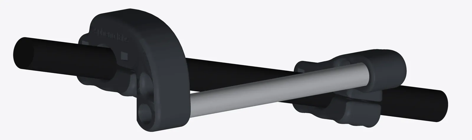
Two clamps per side hold a 16 mm aluminium rail level on the rising tube. Rated 12 kg per side.
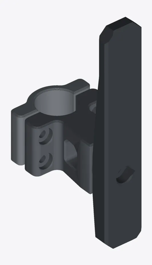
A clamp and toothed post that give the bag’s lower strap something to hold, set in 15° steps.
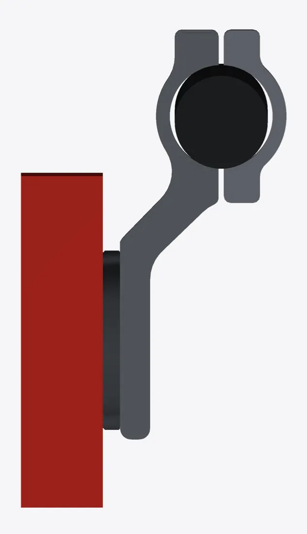
A slim strip drops from the rack’s rear loop to a quarter-turn socket. About 10 g of plastic.
03 / The rail, version by version
Each version answered something: a measurement, a stress hotspot, a print that didn’t feel right. Before v4 the clamps were tied together with a rod. v4 is where the current idea begins.
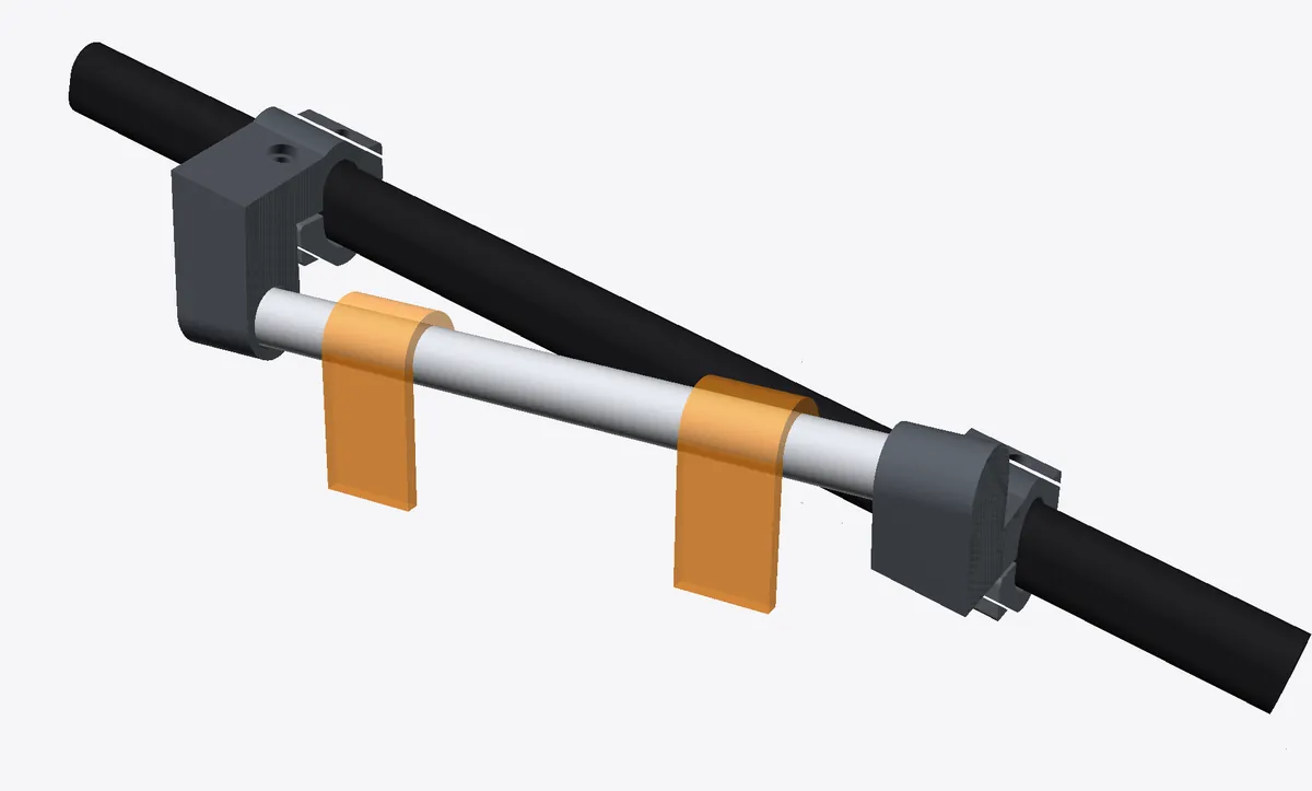
The rail is trapped between two blind sockets, so it needs no fasteners, and an oval bore stops the clamps turning. Printed gauges measure the tube.
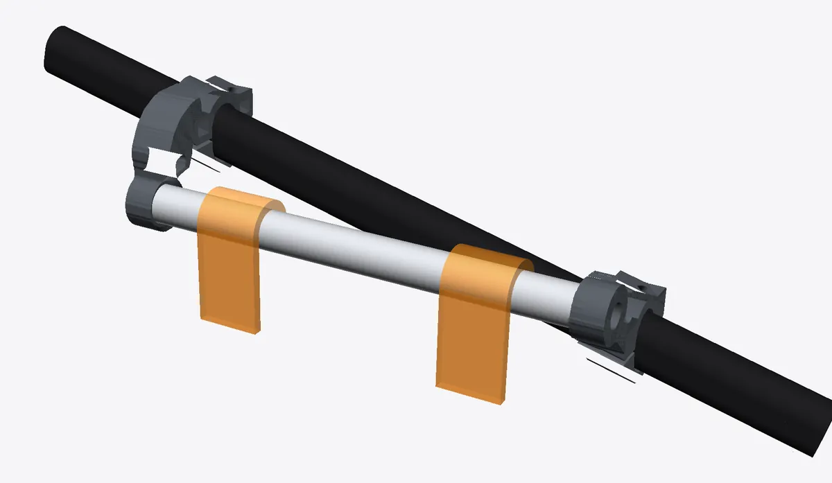
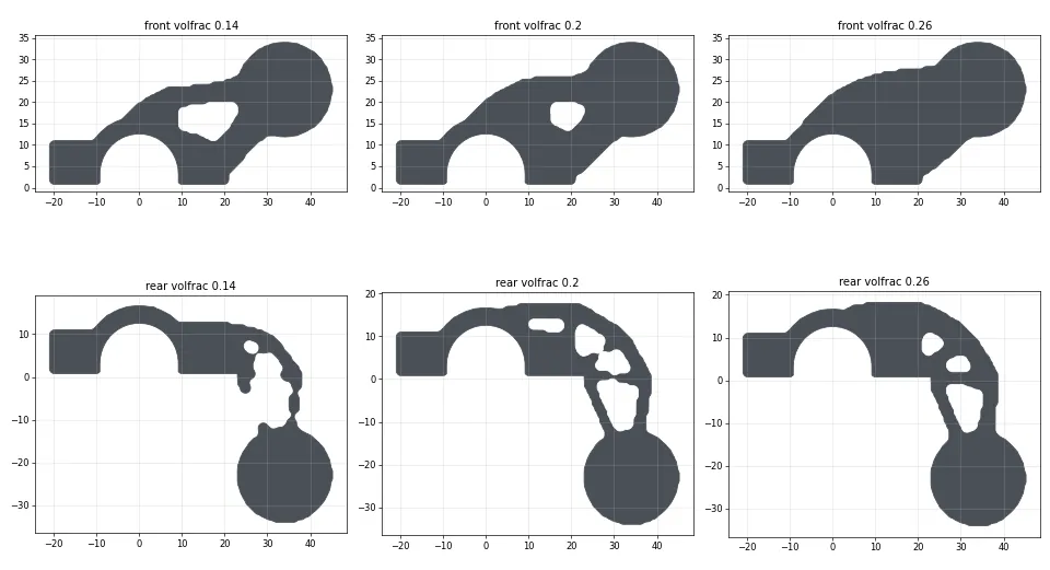
Each clamp’s web is topology-optimised: material goes only where the load flows, which gives the branching shape.
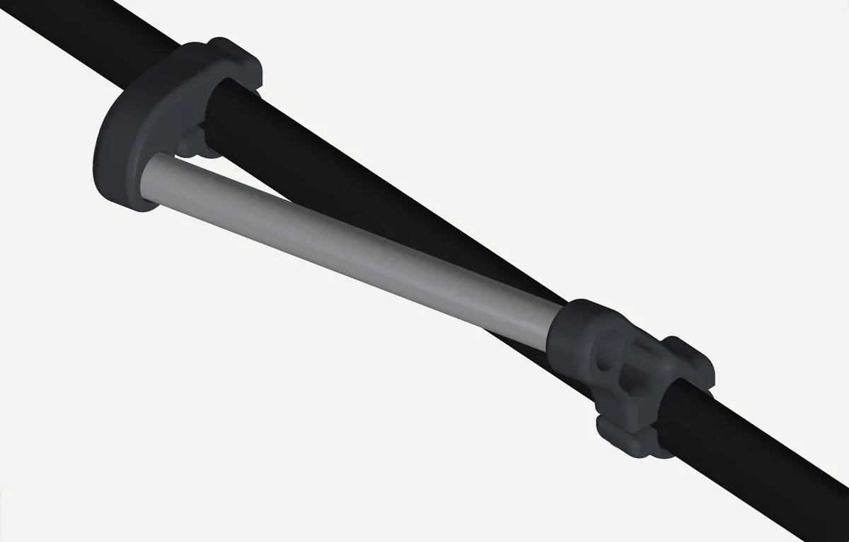
One flowing profile with rounded edges and no supports. Taking out the rear clamp’s 90° bend cut its peak stress from 15.8 to 10.3 MPa.
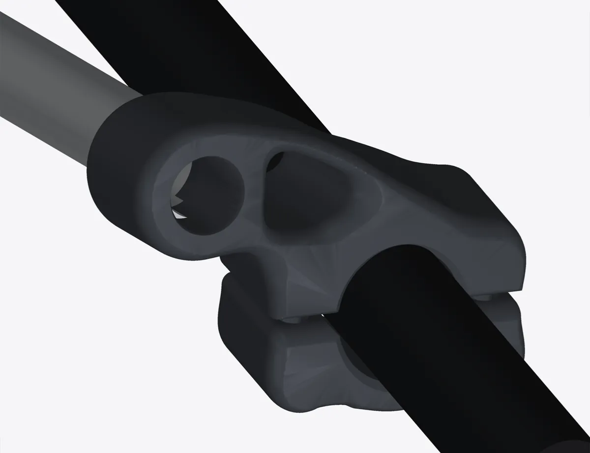
Measured properly, the tube was round, 21.6 mm, not oval. Only friction stops a round clamp turning, so the clamps grew to 26 mm with four M4 screws.
88 g → 157 g of PETG per bike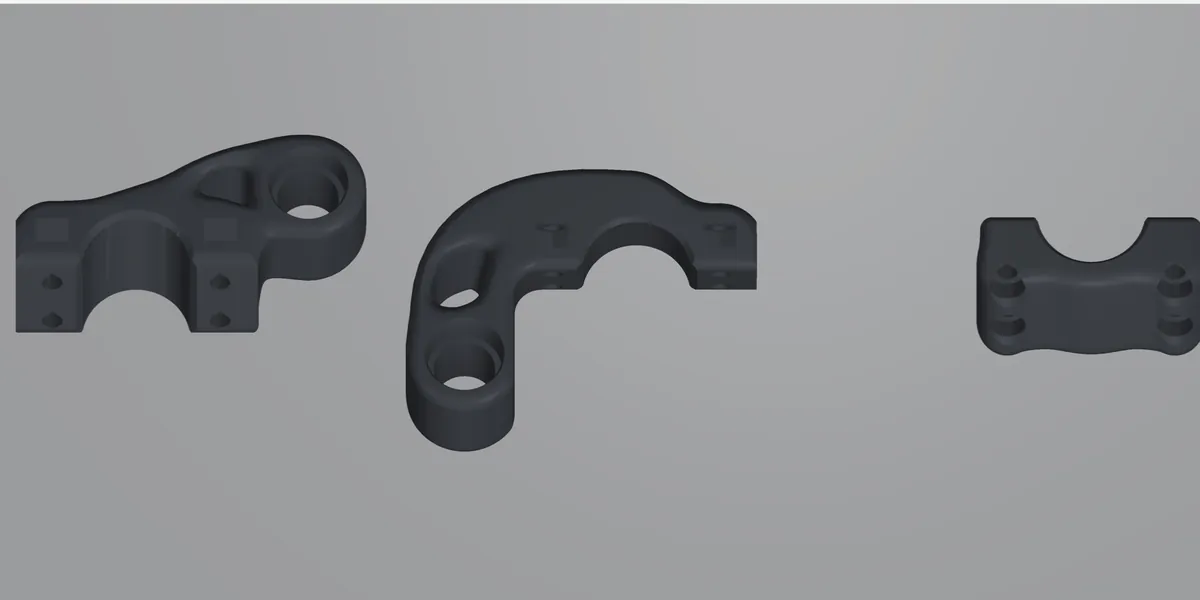
Heat-set inserts gave way to captive M4 nylocs sitting on a shelf. One hex key does everything.
Worst case 13.4 → 12.0 MPa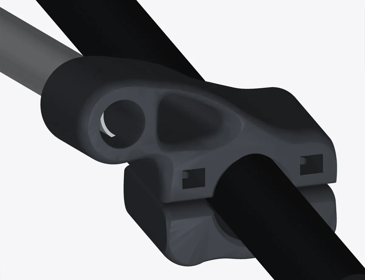
Every bolt moved to 9 mm from the outer edges, about twice its diameter. In v9 one flat was 0.45 mm wide.
12.0 → 10.2 MPa, 213 g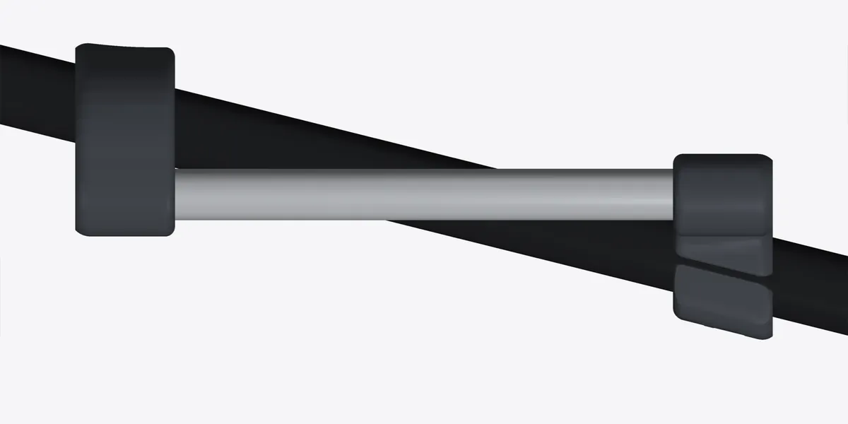
Bolts 9 mm from every edge, including the tube side. 155 mm of exposed rail, with the clamps 192 mm apart.
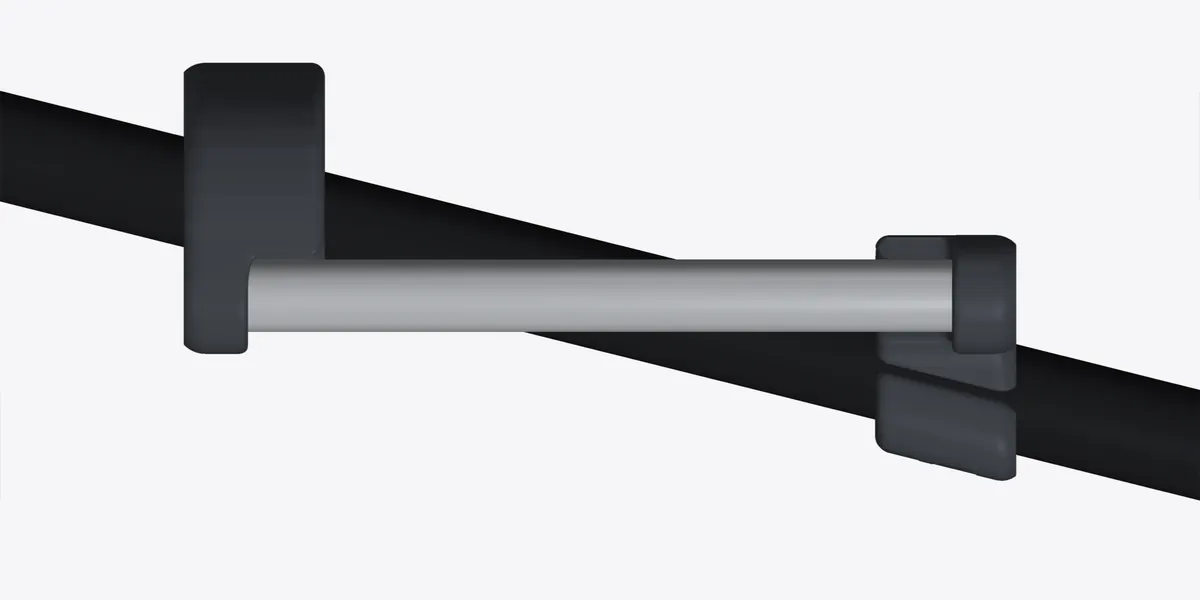
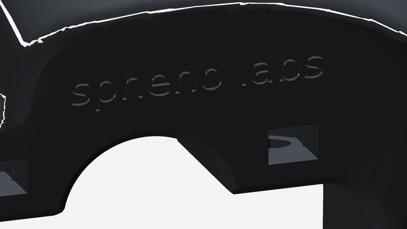
Mounts 35 mm closer together, and a maker’s mark engraved 0.6 mm deep. The tighter layout didn’t earn its keep.
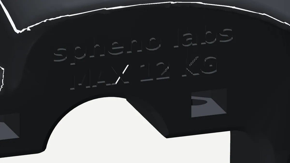
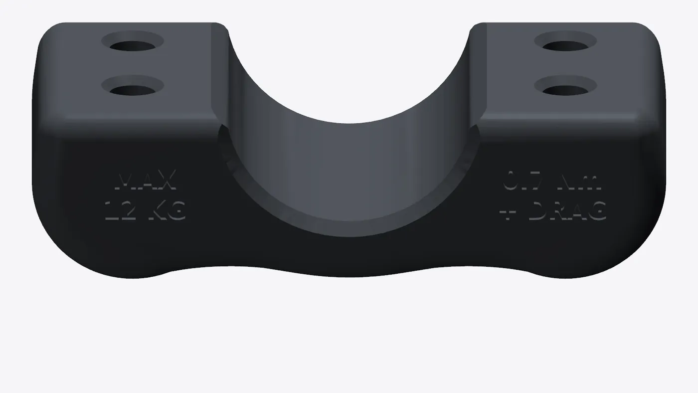
The v11 layout returned, keeping v12’s taller shoulder and lettering, with a rating worked out from grip, strength and the rack: MAX 12 KG per side.
248 g per bike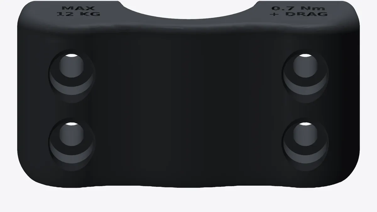
The cap holes had drifted about 3 mm off centre, because the caps followed the level rail rather than the 14° tube. Rebuilt square to the tube, and symmetric.
Cap 10.7 → 7.7 MPa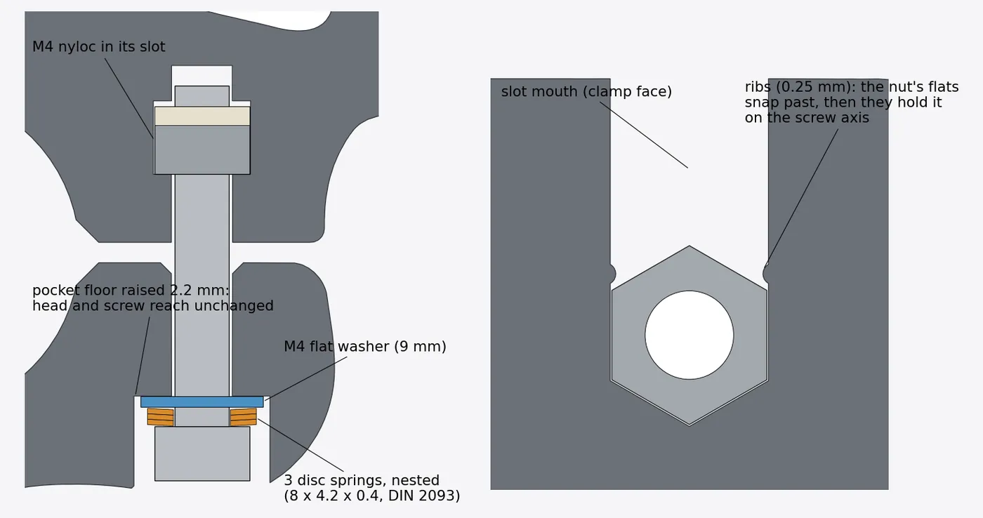
Disc springs and a washer under each head halve the pressure on the PETG, so the clamping force holds up as it settles. Small ribs keep the nuts in their slots.
Head pressure 22 → 10.5 MPa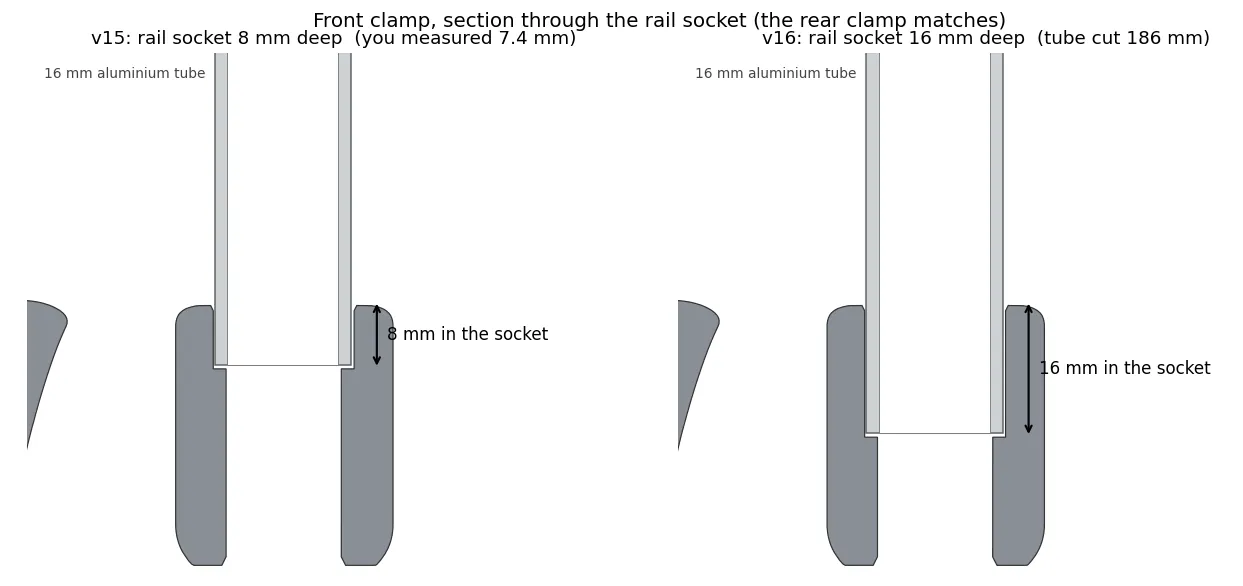
On the printed v15 the rail went only 7.4 mm into each socket. It held, but it didn’t feel secure. Each socket is now 16 mm deep, one rail diameter.
Bearing 1.3 → 0.6 MPa, tilt 3.6° → 1.8°CAD renders and section drawings from each version’s build. v5, v7 and v13b were intermediate builds, folded into the versions shown.
04 / The stress report
Every version is checked with a finite-element model before it is sliced. The final rail’s worst-case peak is 10.7 MPa. PETG Basic is good for about 51 MPa across its layers: a margin of 4.8×.
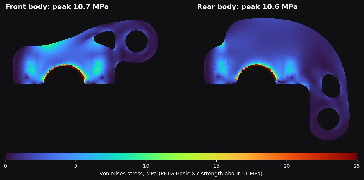
Plane-stress finite elements on each printed part’s outline, with the real thickness measured through the part at every element.
A 10 kg bag at three times its weight with 1.5 g sideways, a pothole taken mid-swerve, on top of 500 N of tension in every screw.
PETG Basic’s strength across the print layers. With PETG HF (34 MPa) the same result is still a 3.2× margin.
Peak von Mises stress, MPa.
| Part | Bag only | Screws only | Both |
|---|---|---|---|
| Front body | 4.9 | 10.3 | 10.7 |
| Rear body | 4.1 | 10.3 | 10.6 |
| Cap | small | 8.3 | 8.3 |
With a wet liner (friction 0.35), each clamp resists 18.9 Nm against the 6.2 Nm a 10 kg bag puts on it at 3 g. After losing 30 % of screw tension it is still 2.1×. Dry, 5.2×.
Whichever limit comes first sets the rating, each with its own margin.
| What limits it | Max per side |
|---|---|
| The rack: MAX 25 KG in total, shared | 12.5 kg |
| Grip: wet liner, settled screws, 3 g pothole, ×1.5 | 14.3 kg |
| Clamp body in PETG HF, strength ÷ 2.5 | 19.9 kg |
| Clamp body in PETG Basic, strength ÷ 2.5 | 33 kg |
| Aluminium rail, 3 g, ×2 on yield | 52 kg |
A build refuses to pass unless every check holds.
MPa, screw tension plus bag, rail v8 to v16.
Grams at 4 walls and 20 % infill. Margin was bought with mass, then held.
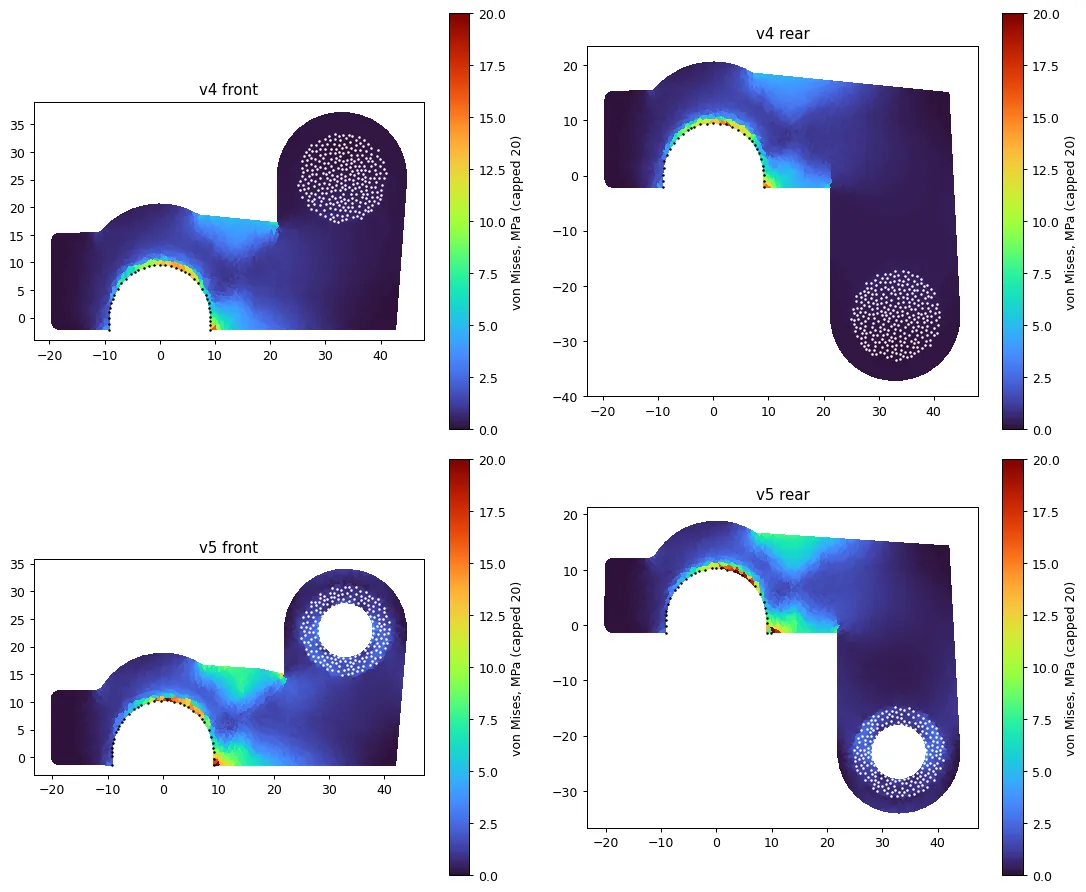
The first maps, on v4 and v5, showed the load crowding into the shoulders of the bore and the root of the arm. Every later profile, from the generative v6 to the sculpted v7, was drawn around those hotspots.
05 / Details
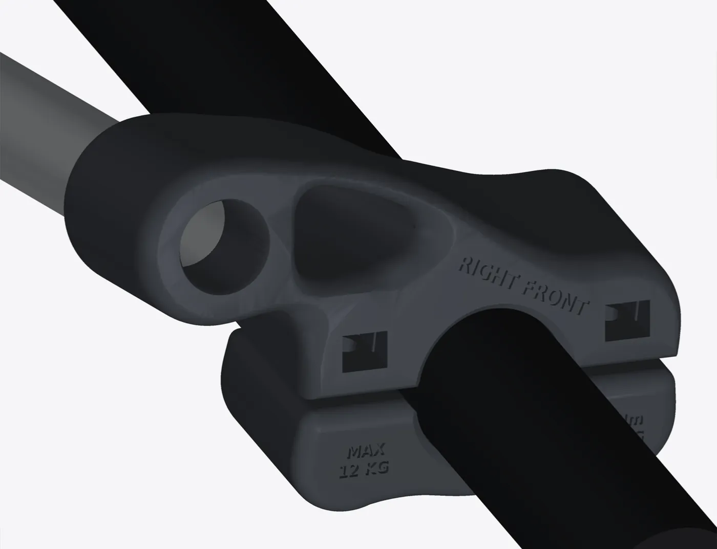
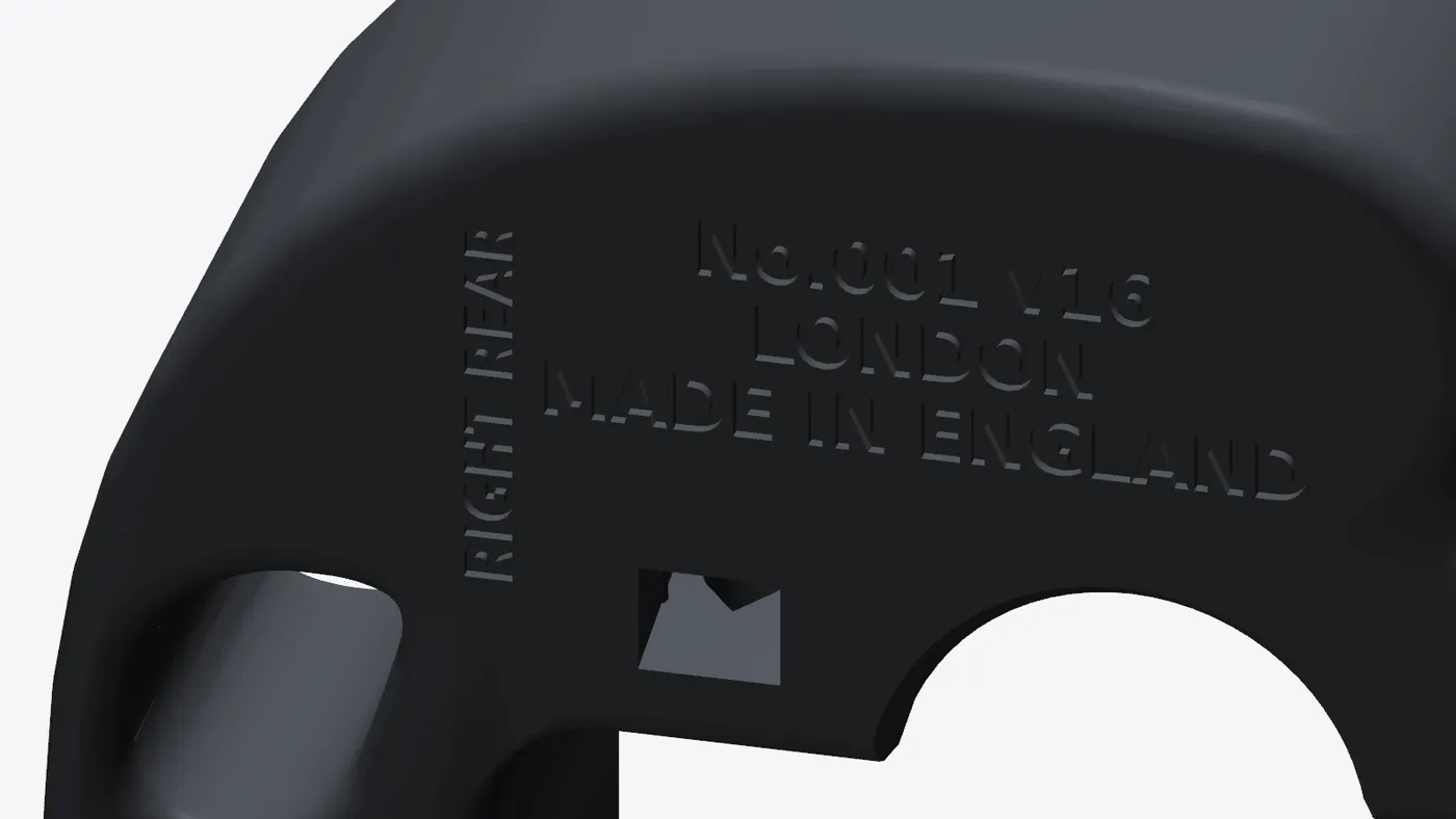
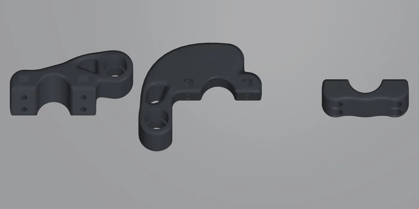
Flat faces down, no supports, a stepped chamfer on every bed edge, and every part engraved with where it goes.
06 / Lower strap anchor
Each bag hangs from its top hooks with its weight about 9 cm out from the back panel, so the bottom swings in towards the tyre. With 10 kg aboard that is about 44 N parked and 190 N over a pothole with a swerve.
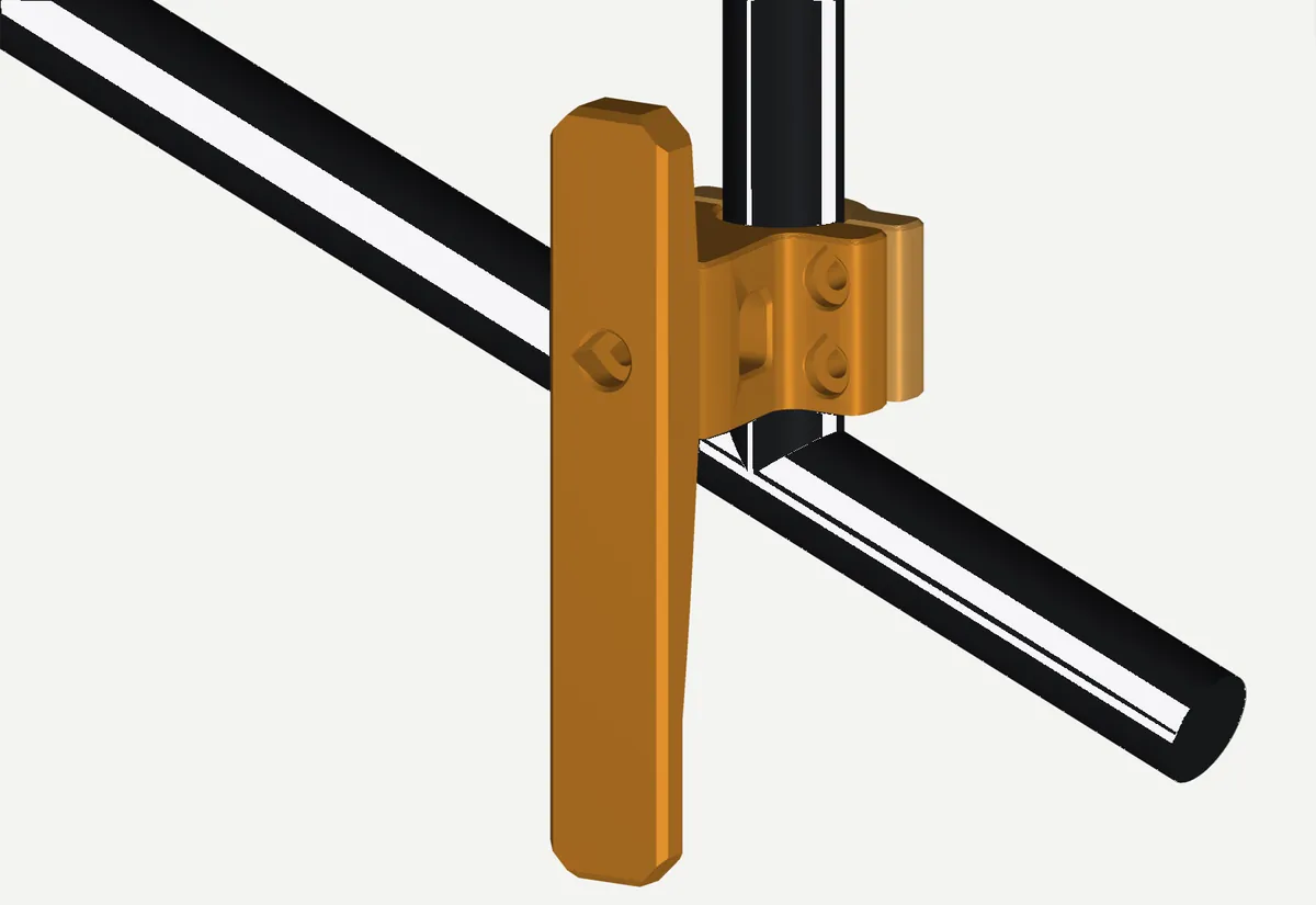
Clamps where it’s needed.It slides along and turns round any rack tube, so the arm points straight out.
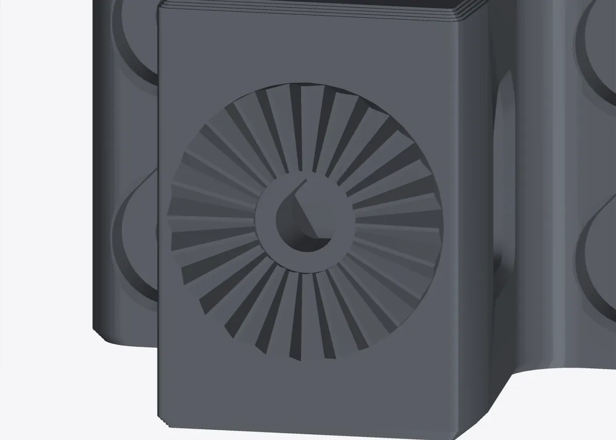
Sets in 15° steps.The 140 mm post turns on a 24-tooth face to stand upright, whatever the tube’s angle.
Flush with the bag.The post’s outer face sits 57 mm out from the tube’s centre, level with the bag’s back panel.
The stress model found the ear roots and a thin nut shelf doing too much of the work.
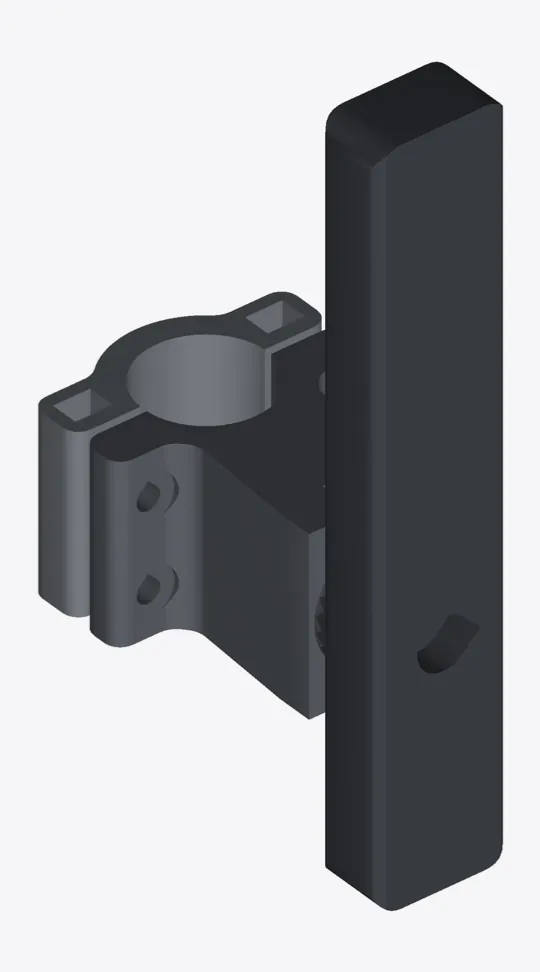
Deeper ears, counterbored heads, nylocs in hex pockets on a solid floor, a post that tapers with its bending moment, and every edge chamfered.
| v1 | v2 | |
|---|---|---|
| Clamp half, peak stress (screws, worst push and braking) | 19.5 MPa | 9.8 MPa |
| Cap, peak stress | 16.1 MPa | 13.1 MPa |
| Mass per side | 64.6 g | 55.4 g |
| Plate, both sides | 147 g, 6 h 25 min | 125 g, 5 h 28 min |
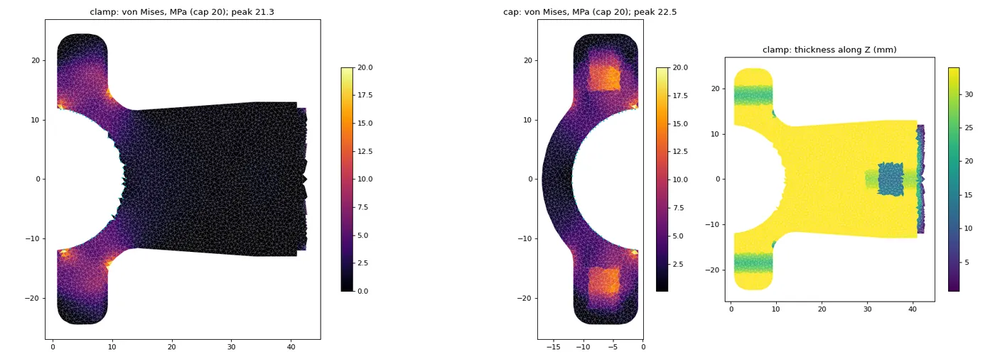
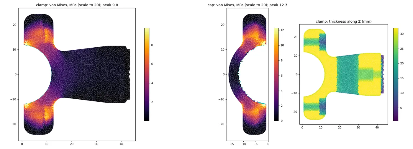
Top: v1. Bottom: v2. Same load cases, same colour scales.
The rack’s lower tubes couldn’t be measured, so they were estimated from Pedibal’s photos. The anchor adjusts rather than assumes. Highlighted in orange.
Tips cut flat by 0.15 mm, so the flanks always carry the load and the printer never draws a knife edge.
07 / SR mini radar mount
v1 gave the radar’s own rubber-strap seatpost mount a printed dummy seatpost to hang from. It worked, but it was bulky and didn’t look like part of the bike. v2 is built the way a manufacturer would do it: a slim strip with a quarter-turn socket at its end.
Clamp, a 31.6 mm dummy post, the stock strap mount and its bands. 39 g.
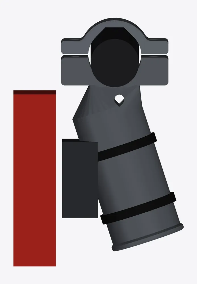
A 10 mm strip drops from a collar on the rear loop. The radar clicks straight on. About 10 g.
| v1 | v2 | |
|---|---|---|
| How the radar attaches | Stock strap mount on a dummy post | Clicks onto a quarter-turn socket |
| Seen from behind | Clamp, post, strap mount, bands | The collar above the radar |
| Screws | 2 × M4 from the top | 2 × M3 from the front, nuts hidden in side slots |
| Printed weight | 39 g | about 10 g |
Countersunk screws from the socket face, nuts in side slots. Nothing shows past the radar.
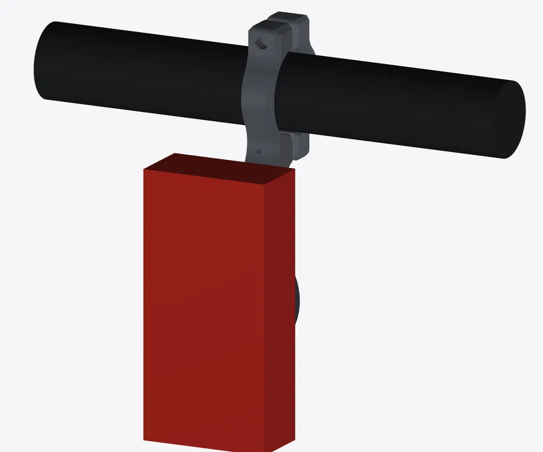
18 g for a plate that includes six test sockets. 1 h 3 min, no supports.
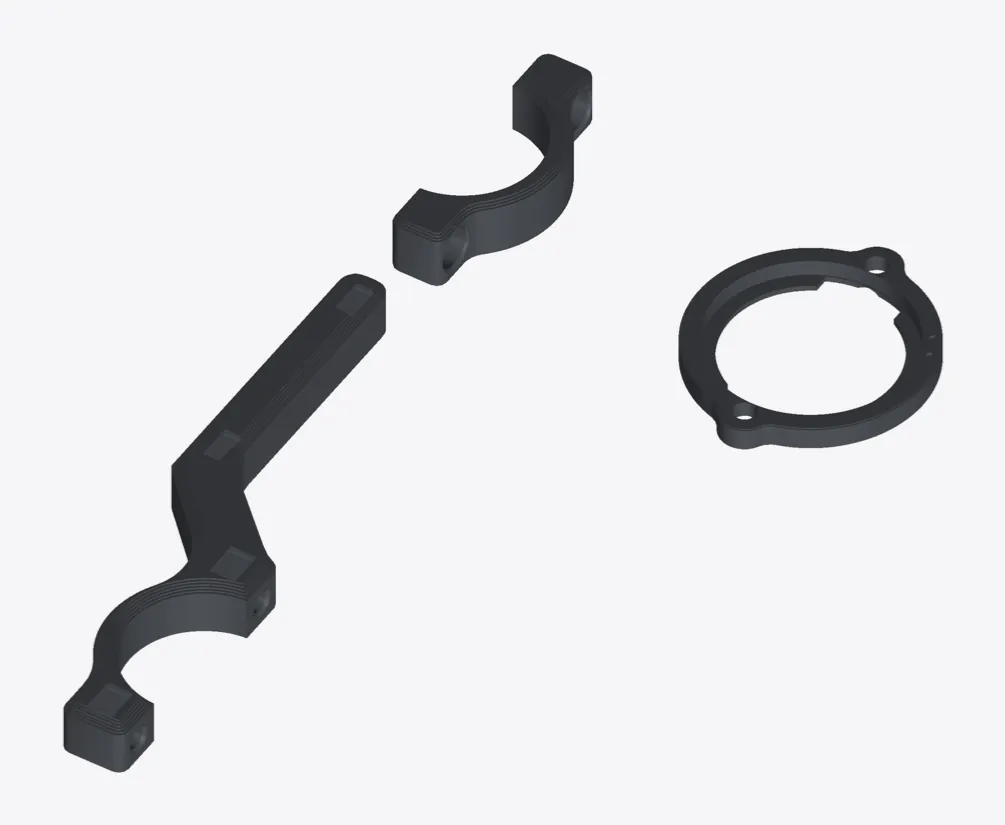
Six test sockets.The SR mini locks 90° round from a Garmin Varia, and the socket dimensions aren’t published. Two slot orientations times three lip thicknesses find the direction and a rattle-free fit in 20 minutes.
Out of the way.The radar hangs with its centre 52 mm below the tube, under the rear light, facing straight back.
Stiff enough.At a 5 g jolt the strip sees about 1.1 MPa.
08 / The whole bike, loaded
Parts that carry bags change how the whole bike rides. So I modelled the loaded bike: frame, hub motor, both batteries, a 75 kg rider sitting at the rear of the bench, and every bag at its real height and position. Then I checked how much weight stays on the front tyre when cruising, climbing and pulling away hard.
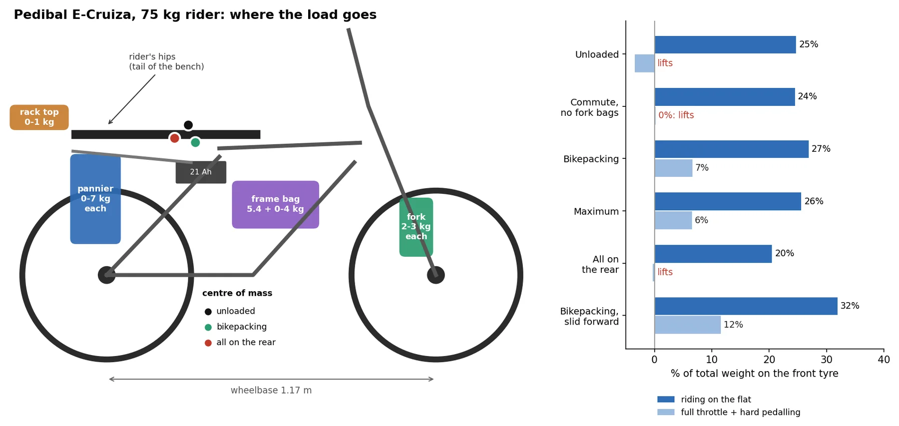
A quarter on the front.With the rider at the rear of the bench, only about 25 % of the weight sits on the front tyre before any luggage goes on.
Full throttle can lift it.Pulling away on full throttle while pedalling hard puts about 420 N through the rear tyre. The unloaded bike needs only about 370 N to lift its front.
Fork bags earn their place.A kilogram on the fork adds nearly three times as much front weight as a kilogram in the frame bag. Panniers behind the rear axle take it away.
| Where | Load |
|---|---|
| Fork bags | 2 to 3 kg each, matched within 0.3 kg |
| Frame bag | Spare battery and charger, plus up to 4 kg of the heaviest kit |
| Panniers | Up to 7 kg each, left and right within 1 kg, heavy items low and forward |
| Rack top | Up to 1 kg, light and bulky |
| Whole rack | 25 kg at most, bags and rail included |
| Loading | Total | Cruising | 15 % climb | Full power |
|---|---|---|---|---|
| Bike and rider only | 108 kg | 25 % | 13 % | lifts |
| Commute: panniers 3 kg, nothing on the fork | 121 kg | 24 % | 13 % | 0 % |
| Touring: panniers 7, fork 3, frame bag +3 | 139 kg | 27 % | 16 % | 7 % |
| Maximum: panniers 9.5, fork 3, frame bag +4, rack top 1 | 146 kg | 26 % | 15 % | 7 % |
| Everything on the rear: panniers 9.5, rack top 4 | 138 kg | 20 % | 9 % | lifts |
| Touring, sliding 20 cm forward to pull away | 139 kg | 32 % | 21 % | 12 % |
Full power: full throttle plus hard pedalling from a standstill. Everything on the rear also takes the rack over its 25 kg rating.
09 / What it costs to make
Priced by what each part actually uses: filament by the gram, electricity by the kilowatt-hour, printer wear by the hour, and hardware by the piece rather than the pack.
| Part | PETG | Print time | Energy | Filament | Electricity | Printer wear | Hardware | Total |
|---|---|---|---|---|---|---|---|---|
| Pannier rail v16, both sides | 267 g | 11 h 36 min | 1.30 kWh | £3.13 | £0.34 | £0.85 | £17.48 | £21.80 |
| Lower strap anchor v2, both sides | 125 g | 5 h 28 min | 0.62 kWh | £1.47 | £0.16 | £0.40 | £1.91 | £3.94 |
| SR mini mount v2 | 18 g | 1 h 3 min | 0.14 kWh | £0.21 | £0.04 | £0.08 | £0.11 | £0.43 |
| All three | 411 g | 18 h 7 min | 2.05 kWh | £4.81 | £0.54 | £1.33 | £19.50 | £26.18 |
Power is the smallest line.54p for all three parts. Even at 30p a unit it would be 62p.
Hardware is the biggest.On the rail, the aluminium tube (£6.31) and the disc springs (£5.52) cost more than the plastic. Plain washers instead of springs save £4.95.
About 1.6p a gram, printed.Filament, electricity and printer wear together come to about £0.016 for every gram that comes off the bed.
PETG at £11.72/kg (SUNLU). Electricity at 26.32p/kWh, the Ofgem price cap for October to December 2026, GB average. Bambu quotes about 95 W for the A1 printing PLA; I've allowed 110 W for PETG's hotter bed, plus heat-up. Printer wear at £0.073 an hour: the A1 at £238 over 5,000 hours, plus nozzle and build plate. Hardware priced per piece from the packs bought. Excludes prototypes, tools, delivery of spares and my time.
10 / The workflow
The method matters more than any one part. Every design here is a script, not a drawing, so a new measurement means a rebuild rather than a redraw.
Callipers, a phone level and printed gauges. Callipers held vertical on a tube sloping at 14° read 22.44 mm; the true diameter is 21.6 mm, and the slope accounts for the rest (21.6 ÷ cos 14° = 22.26 mm).
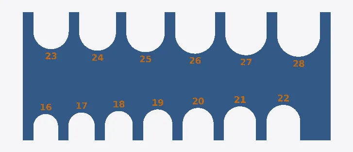
Parametric OpenSCAD and Python. Tube size, angle, spacing, screw sizes and filament are all parameters.
Every build tests fit, install path, clearances, hex-key reach and overhangs, and fails if any one doesn’t hold.
Finite-element checks on every part, and sweeps to see where material earns its place.
Plates are sliced from the command line with the same printer profile every time, so weight and print time are known before the printer starts.
The printed v15 showed the rail sitting 7.4 mm into its sockets. That one measurement became v16.
I set the requirements, measured the bike, printed and fitted the parts, and decided what changed next.
Claude, an AI model made by Anthropic, wrote and ran the parametric models, geometry checks, simulations and slicing between versions, and reported the numbers back to me.
11 / Where it stands
Three parts, three version numbers. The rail has been printed and fitted; the anchor and the radar mount are designed, checked and simulated, and still to be proven on the bike.
| Part | Version | PETG as printed | Print time | Key figure | On the bike |
|---|---|---|---|---|---|
| Level pannier rail | v16 | 267 g, full set | 11 h 36 min | 10.7 MPa worst case; 12 kg per side | v15 printed and fitted; v16 is the fix from that fitting |
| Lower strap anchor | v2 | 125 g, both sides | 5 h 28 min | 9.8 MPa clamp peak | To be confirmed |
| SR mini mount | v2 | 18 g, with six test sockets | 1 h 3 min | About 1.1 MPa in the strip at 5 g | To be confirmed |
Slicer figures for SUNLU PETG at 0.20 mm, 6 walls and 25 % gyroid on a Bambu Lab A1.
About this page
This project isn’t for sale, and I’m not offering kits, files or fitting. The images are CAD renders and simulation plots from the design files, not photographs. Rack tubes in some renders are estimated from Pedibal’s photos.
Printed parts on a moving bicycle need regular checks. Nothing here is advice to copy it.